When selecting an open gear lubricant for use in a particular application, the method of application used must be considered. The typical methods of application used in open gear systems are:
-
Spray/atomization systems
-
Gravity feed or drip feed
-
Oil bath (splash and idler immersion systems)
-
Hand, brush or pour it on
Generally, if the open gear lubricant is to be applied by a drip system, force-feed lubricator or spray system, it must be sufficiently fluid to flow through the application equipment. For brush applications, the open gear lubricant must be fluid enough to be brushed evenly on the teeth. In any case, during operation, the open gear lubricant must be viscous and tacky enough to resist squeeze-out from the gear teeth.
When open gears are lubricated by dripping into a splash pan or through the use of splash and idler immersion systems, the open gear lubricant must not be so heavy that it channels as the gear teeth dip into it. Finally, when open gears are lubricated, the consistency or grade and its ease of pumpability must permit easy application under the prevailing ambient conditions.
Spray/Atomization Systems
The most common type of spray/atomization system used in the lubrication of open gearing is the intermittent mechanical spray system. Its usage depends upon the open gear lubricant remaining on the gear teeth through several revolutions. Intermittent spray systems utilize metering valves that direct the lubricant to an air/grease nozzle that sprays the lubricant onto the open gears with the assist of air pressure. The basic components of this type of system are a pump, a controller, a metering valve, a spray manifold and spray nozzles.
The operation of this type of system is very straightforward. A signal from a controller turns on the pump to supply the open gear lubricant to a positive-displacement metering valve. The metering valve can be a progressive, two-line or injector type. The metered lubricant is sent down a passage in a spray manifold, where the open gear lubricant is directed to a nozzle.
A second passage of pressurized air (usually in the range of 80 to 120 pounds per square inch) is directed to the same nozzle. This pressurized air blows the open gear lubricant out of the nozzle onto the open gear. After a predetermined amount of open gear lubricant is dispensed, both the air system and the pump shut off until the next lubrication cycle. Usually there is a delay in shutting off the air so as to ensure that the open gear lubricant has cleared the nozzle. The purpose of this is to remove the open gear lubricant out of the nozzle tip, thus preventing it from drying and clogging the nozzle.
The spraying time should equal the amount of time it takes for one or two revolutions to ensure complete coverage. Periodic inspections must be made to ensure that a sufficient amount of open gear lubricant is being applied to provide proper protection. Two hours is the maximum interval time permitted between applications per the AGMA 9005-D94 guidelines.
The amount of open gear lubricant to use is dependent upon the application the open gear is being used in (mills, kilns, dragline, etc.) and the pitchline velocity of the gearing, the rated electrical power draw on the electric motor powering the gear (for mills and kilns), the type of gearing, and the type of open gear lubricant that is to be applied. In many applications, your lubricant supplier can recommend the starting amount to use.
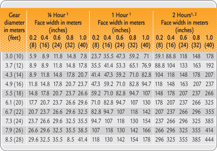
These application rates are expressed in grams per centimeter face width per hour. In lieu of a starting recommendation given by the lubricant supplier, the AGMA has issued lubricant quantity guidelines in the AGMA 9005-D94 standard that can be used for intermittent methods of application.
 |
|
1) The spraying time should equal the time for one and preferably two revolutions of the gear to insure complete coverage. Periodic inspections should be made to insure that sufficient lubricant is being applied to give proper protection.
|
| 2) Two hours is the maximum interval permitted between applications of lubricant. More frequent application of smaller quantities is preferred. However, where diluents are used to tin lubricants for spraying, intervals must be so short as to prevent diluent evaporation. |
|
Table 1. Lubricant Quantity Guidelines for Intermittent Methods of Application (ref. 1)
|
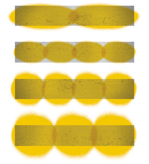
To ensure that a correct amount of open gear lubricant is being applied and operation reliability is being maintained, it is important that you maintain a perfect spray pattern without any gaps. Distribute the open gear lubricant evenly over the entire height and width of the tooth flank on the loaded side of the gear.
The number of spray nozzles to use for a given application is determined by the gear width. Typically, four to six spray nozzles are required; they must be properly spaced to provide adequate lubricant coverage across the entire face of the gear teeth.
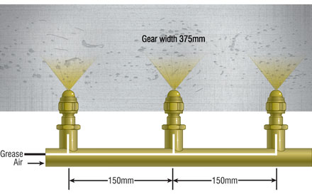
As a guideline, for slow-speed open gearing operating up to 2,000 feet per minute (10 meters per second), the end nozzles should be placed 2 to 2.5 inches (50 to 65 millimeters) from the gear face edge with the remaining nozzles spaced 5 to 7 inches (130 to 180 millimeters) from center. Nozzle location is also a function of the spray pattern.
Spray nozzles are generally positioned to direct the open gear lubricant at the loaded profiles of the gear teeth (not the pinion) at a maximum distance of 6 to 8 inches (150 to 200 millimeters) from the gear teeth.2 The correct spray pattern on the tooth flanks and an illustration of the correct spacing of spray nozzles are illustrated in Figures 1 and 2.
 |
|
Figure 1. Correct Lubricant Spray Patterns on Tooth Flanks.
|
 |
|
Figure 2. Placement of Spray Nozzles.
Example of three-nozzle spray bar with spray nozzle spaced apart at 150 mm. |
 |
|
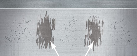
Figure 3. Inadequate Spray Pattern on the Tooth Flank.
Inadequate spray patterns normally lead to scuffing in these highlighted areas. Additional spray nozzles correctly spaced and higher air pressure is required to improve the lubrication film.
|
The air pressure to the spray bar also must be properly set; otherwise, the open gear lubricant will not be atomized correctly. Too low of air pressure will result in a splattering, lumpy or stringy appearance (as illustrated in Figure 3), while too high of air pressure will tend to blow the open gear lubricant off of the gear. For most open gear lubricants, the air pressure seating must not be set lower than 75 psi (35 kilopascals or 5 bar) and not higher than 90 psi (42 kpa or 6 bar).
Even if the spray nozzles are monitored using control flow mechanisms, periodic checks of the spray pattern are recommended as part of maintaining adequate and even coverage of the open gearing on the gear face.
Spray bars have many different designs, and many of the older spray systems do not allow easy access to check the spray pattern while the open gearing is operational. If the spray bar does not swing out or open outward with the door, the safest way to check the spray pattern is when the machine is shut down. A recommended procedure for inspecting spray patterns is as follows:
-
Ensure isolation procedures are adhered to, then open the inspection door and place a clean piece of cardboard or paper on the gear set, where the spray nozzle atomizes the open gear lubricant onto the gear set.
-
Operate the lube system and check the lubricant coverage on the cardboard or paper. The coverage should overlap from one spray nozzle to the next, and there should not be any gaps within the appropriate height and width to cover the load-carrying gear teeth.
-
If gaps are found, the air pressure, spray angle and spray cap need to be adjusted to obtain the appropriate coverage.
-
Once the adjustments have been made, repeat the process until the perfect spray pattern (as depicted in Figure 1) is achieved.
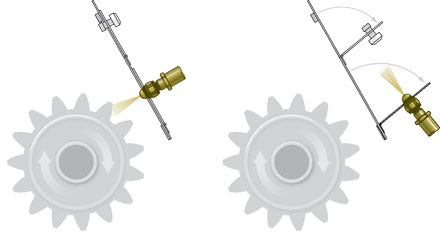
If the spray bar requires changing, the spray bar design should be altered so that spray pattern can be checked during equipment operation (as shown in Figure 4).
 |
|
Figure 4. Recommended Spray Bar Design to Allow Easy Checking of Spray Pattern
|
 |
|
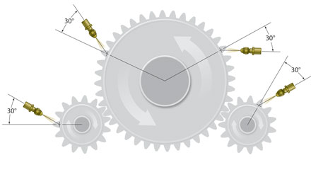
Figure 5. Spray Bars Can be Located at Four Different Directions of Rotation
|
The spray bar should be set at a 30-degree angle to spray the open gear lubricant onto the drive or loaded side of the pinion or girth gear. Setting the spray angle at 30° (as shown in Figures 5.) will achieve a very good distribution of the lubricant in an upward or downward direction, always to the load-carrying tooth flank.
The spray nozzle distance set back from the gear is approximately 8 inches plus or minus 2 inches (200 millimeters plus or minus 50 mm), depending on the air pressure and tooth height. The width of the gear tooth will determine the amount of spray nozzles required to adequately lubricate the gear drive.
To further ensure that the proper amount of lubricant is being applied once the spray bar nozzles and patterns are set, it is recommended that the amount of lubricant being expelled from each injector be weighed. Over time, injector spray nozzles do not deliver the appropriate amount of lubricant per cycle that they are designed to deliver.
Too much open gear lubricant being applied can cause waste, while under-lubrication can lead to increased wear and eventual component failure. The amount of lubricant that needs to be expelled from each injector can be obtained from the manufacturer of the automatic lubrication system. For example, a Lincoln SL-1 style injector typically expels 0.046 ounces (1.31 grams) per cycle of lubricant.
The timer settings on the automatic lubrication system should eventually be set to the shortest frequency depending upon the type of open gear lubricant used. For asphaltic and high-viscosity synthetic high-viscosity base fluids, the typical time-setting interval is 10 to 20 minutes, while for semi-fluid greases and gel/polymer-thickened type open gear lubricants, the typical time-setting interval is 15 to 30 minutes.
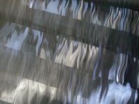
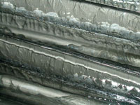
A strobe light can be used to check the appearance of the gears during operation. The strobe light should be set at the same speed that the gear is turning. A well-lubricated gear will have a dark color to semi-transparent appearance depending upon the type of open gear lubricant being used, and strings of lubricant will appear as the gear and pinion teeth separate. An over-lubricated gear will be black with excess lubricant dripping, flinging off or built up on the teeth and root zones of the gear.
Taking temperature readings across the gear face using a non-contact thermometer can be additionally done to check if the open gearing is being properly lubricated. An even temperature across the gear tooth indicates that the gear is being properly lubricated.
In addition to being used to check for proper lubrication, strobe lighting and temperature reading can be used to check for misalignment. Any misalignment results in less contact across the meshing gears, resulting in increased wear. Roughly a 30 degree Fahrenheit difference across the gear tooth and darker to lighter areas of lubricant across the contact film indicates misalignment.
Gravity-Feed or Drip-Feed Systems
Gravity-feed or drip-feed systems are found on mills, kilns, shovels, draglines and excavators. These systems consist of one or more oilers, cascade pans, pressurized feed lines or applicator wheels. They allow the open lubricant to drip into the gear mesh at a set rate. This method of application is limited to open gearing with pitchline velocities of 1,500 feet per minute (7.5 meters per second) or less.
For these types of systems, asphaltic, high-viscosity synthetic oil open gear lubricants are generally used. If pressured feed lines or applicator wheels are used in these systems, a semi-fluid grease or gel/polymer-thickened type of open gear lubricant can be used.
Oil Bath (Splash and Idler Immersion) System
Oil bath systems are the simplest method of lubricating open gears. The gear or an idler in mesh with the gear is allowed to dip into the open gear lubricant, carrying it around to the mesh. Idler immersion systems are generally limited to open gear systems with pitchline velocities below 300 feet per minute (1.5 meters per second). Some systems will also contain recirculating pumps and filtration systems. Splash and idler immersion system can be found on mill and kiln applications.
As a general recommendation, asphaltic, high-viscosity synthetic oil, semi-fluid grease type and gel/polymer type open gear lubricant can be used in these systems. If a semi-fluid grease type of gel/polymer is used, the open gear lubricant must be semi-fluid to fluid in consistency. If the open gear lubricant is an asphaltic or high-viscosity synthetic base fluid type, the viscosity of the fluid should be a minimum of 1,000 centistokes (cSt) at 40 degrees Celsius.
Hand, Brush or Pour it On
This method of application is one of the oldest and most dangerous methods used to apply open gear lubricants. It has been used to apply open gear lubricants on mills, kilns, shovels, draglines and excavators. Generally, asphaltic type and high-viscosity synthetic type open gear lubricants are applied by this method.
It can result in not only the improper amount of open gear lubricant being applied, but also can result in the introduction of contaminants into the gearing. Further application by this method while the open gearing is operational can result in safety considerations that can result in injury or even death to the person applying the open gear lube.
Lubricating Film Thickness and Selection Criteria
The primary lubrication regime required to lubricate open gearing is elastrohydrodynamic (EHD) lubrication. According to the EHD theory, the critical factor is the open gear lubricant’s film thickness. The open gear lubricant’s film thickness is dependent upon the dynamic viscosity of the open gear lubricant at operating temperatures, average surface velocity of the gear temperature, the loads and geometry of the gearing, etc.
It has been established that the lubrication condition which exists in most gears is predominately elastrohydrodynamic. Gear teeth are subject to enormous contact pressures over relatively small areas (possibly as great as 435,000 psi), and yet they are successfully lubricated with very thin films of lubricant. There are two reasons for this:
-
The high pressure causes the surfaces to deform elastically and spread the load over a wider area.
-
The viscosity of the lubricant increases considerably with pressure, thus increasing the lubricant’s load-carrying capacity.
Once the film thickness is determined, another important parameter which must be calculated is the Lambda ratio. This ratio is defined as the ration of EHD film thickness of the lubricant to the composite surface roughness of the contacting metal surfaces.
As the Lambda ratio approaches 1 (i.e. the film thickness is of the same order as the surface roughness), it can be expected that there will be increased contact between the two contacting gears.
It should be noted that this calculation is based on the base oil viscosity of the open gear lubricant only. It does not take into account any film thickness contribution that may be made by the open gear lubricant’s thickener system or its solid lubricants. In addition, some types of open gear lubricants – such as grease-like and gel/polymer-thickened types – may contain light-viscosity base fluids.
These light-viscosity base fluids are used as a cutback of the heavy-viscosity base fluids present in the formulation in order to enhance the pumpability of the product during low-ambient-temperature conditions.
The light-viscosity base fluids are volatile and dissipate under operating conditions. Subsequently, the base viscosity of these open gear lubricants increases, generating a tacky, durable lubricant film that adheres to the gearing.
 |
|
Figure 6. Properly Lubricated Open Gear
|
 |
|
Figure 7. Over-lubricated Open Gear
|
Besides taking into consideration the lubricant film thickness provided by the open gear lubricant being selected, other considerations that must be taken into consideration when recommending the proper type, grade and amount to be applied are:
-
The OEM requirements.
-
The type of open gear application – mills, kilns, shovels, draglines, etc.
-
The ambient temperature encountered in the area in which the machine operates.
-
The climate condition in which the machine operates – ice, snow, wet, dusty.
-
How the lubricant is being applied.
-
If applied by a spray or automatic lubrication system, the type of lube system that is installed – Farval, Lincoln, Worner, Droppsa, etc.
-
The type and ratio of the pump utilized on the automatic lube system.
-
The width of the pinion gear.
-
Whether the gearing is a double or single pinion
-
The power rating on the electric motor.
-
The position and number of spray nozzles.
Once all of these conditions are known, the proper open gear lubricant for the given application can be selected based upon the different topics, methods of application and characteristics discussed in this paper.
Finally, when switching open gear lubricants or applying open gear lubricants on new equipment where no prior lubricant was used, the following procedures should be followed:
Procedure to follow on new equipment:
-
Clean all coating and debris from the gears.
-
Coat the gear and pinion with a light film of open gear lubricant by some sort of spray method.
Start-up procedure:
-
Run equipment slowly under no load to verify that there is lubricant throughout the entire load zone.
-
Gradually increase speed and load while turning on the automatic lube system.
-
Monitor continuously until a proper coating is maintained.
For spray systems:
-
Prior to startup, purge the lube lines and check spray patterns for complete coverage.
-
Adjust the air pressure and volume as needed.
For drip systems:
-
Most open gear lubricants are designed to adhere where they are applied. Drip tubes should be spaced no farther than 2 inches apart.
Procedure to follow when switching from one type of open gear lube to another:
Although it is best to completely clean the gear, pinion and gear guards, conversion of one type of open gear lubricant to another can be made by applying the open gear lubricant to be used directly over most existing applications.
Procedure:
-
Purge the lube lines thoroughly.
-
Start the timing settings 50 percent higher than the operational settings to ensure all of the lines are purged and flushed and have built up a sufficient lubricant coverage film before reducing the lubricant consumption rate to the operational settings.
-
Readjust the timer to maintain an adequate lubricant film. The lubricant quantity should not be reduced abruptly but at five-minute intervals of 150 to 200 hours for mills and 100 to 150 hours for shovels, draglines and excavators.
-
Product performance should be monitored.
-
When reducing consumption quantity to the control unit of the spray system, it should be set to ensure the intervals between spray cycles are as short as possible. Short and frequent spray cycles ensure the lubricant is supplied evenly to the component; this increases functional reliability.
-
Adjust the air pressure and volume as needed.
-
Inspections of the lubricating systems, tooth flank conditions and the spray pattern are required to ensure reliable operation. The spray system should be maintained thoroughly in accordance with the manufacturer’s instructions.
References
1) ANSI/AGMA 9005-D-94 – “Industrial Gear Lubrication, Table 10”, page 10
2) Ibid, page 11
About the Author
Lawrence G. Ludwig Jr. is the chief chemist/technical director for Schaeffer Manufacturing. To learn more, visit www.schaefferoil.com.


