The harsh work environments in which some industrial equipment is situated can lead to short life cycles and unpredictable failures, such as those found in mining or offshore oil and gas industries. While manufacturers may offer and honor time-based warranties, they cannot predict accurately the lifespan of the equipment. Moreover, replacement of equipment under warranty by the manufacturer does nothing to mitigate the cost of unscheduled downtime and lost revenues.

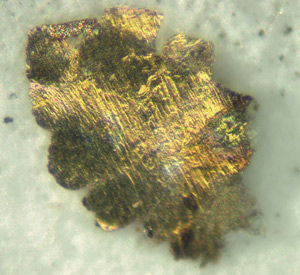
This Macro-2-Micro one-shot image of an
oxidized particle on a filter patch shows
surface detail that would not be visible
using a microscope without extended
focus capability.
A solution to this problem lies with the various fluid and particle condition monitoring tests that convey information about the current mechanical state of a system. In the front line of these is the collection and analysis of wear debris particles taken from a component’s lubricating or power transmission fluid. Wear debris analysis is so important because sampling is relatively simple to execute, the test is non-destructive and it can give a vital early warning of incipient component failure.
Particle Sizing and Counting Hardware
Particle counts can be determined using optical instruments. The first of these methods is to use a microscope. Particles are precipitated from fluid samples, which are taken from the component’s lubrication system, by draining through a filter patch. Particles are then interactively sized and counted manually using a microscope. However, because of its labor-intensive nature, this method was replaced by automatic particle counters (APCs) in the 1960s.
First-generation APCs contain a laser light source and a detector, which are separated by an optical cell. The oil sample flows through the cell, and when a particle passes through it, an area of light is obscured. The detector senses the loss of light and outputs a voltage. The voltage pulse generated increments the particle count, and the height of the pulse is used to determine the size of the particle.
These APCs have the disadvantage of not being able to distinguish between multiple particles, and because they are “blind” to the shape of the particle, they are only able to report size in terms of a projected area equivalent diameter. That is, size is defined as the diameter of the disc with an area equivalent to the area of the particle’s shadow. This method can lead to errors because the estimated projected area equivalent diameter is a function of the shape of the particle. In other words, the size of the particle is increasingly underestimated as the shape becomes more elongated. In particular, long, thin particles will be systematically undersized to the point where they may slip into a size range smaller than their actual size indicates or even disappear from the count all together.
A second generation of APCs has emerged that operates using micro-second duration-pulsed lasers. This has the effect of freezing the image of the particles present in the optical cell. The light sensor associated with first-generation APCs is replaced by a charge-coupled device (CCD) sensor. In this way, the system is able to collect the silhouette images of multiple particles. Image processing is then used to count and size the particles.
Various contaminants such as varnish or fibers have optical properties that make them invisible to APCs. These contaminants can build up to critical levels without being detected by the APC.
The ASTM D7596-11 standard test method for automatic particle counting and particle shape classification of oils using a direct-imaging integrated tester gives a list of 11 possible sources of error when using a second-generation APC. A relatively high level of skill and experience not generally available onsite would be needed to detect or control these errors.

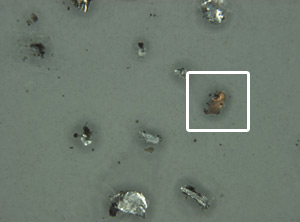
This image of magnetic plug debris seen at
40x magnification includes a particle that an
inexperienced technician might mistake
for brass or copper.
Innovative Particle Imaging Hardware
New technology has recently become available that solves many of the practical limitations imposed by the traditional design of the microscope when viewing and capturing images of both macroscopic and microscopic particles. The new technology is dedicated to optimizing the lateral and axial resolution available at the magnifications and resolutions required to reproduce images in an electronic form, whether that is for data storage, printing in reports or for on-screen viewing. In this way, images can be generated in which the depth of focus and field of view are optimized for viewing macroscopic and microscopic particles at the same magnification.

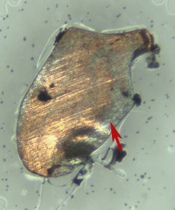
Image-2-Information software reveals
that because the particle has a
non-uniform surface color, it is
not brass or copper but instead
a heated particle, indicating early
stages of lubricant starvation.
With the new technology, it is possible to acquire sharply focused images over a much wider range of magnifications and resolutions than when using a traditional microscope and without resorting to motorized stages or specialized software in order to create a wider field of view or extended depth of focus.
The image above shows a one-shot image of an oxidized particle on a filter patch. Without such a sharp image allowing the surface detail to be seen, this particle might be mistaken for a brass/copper fatigue particle, whereas it is a hybrid particle with striations associated with severe sliding and colors indicating heating.
This new technology can be implemented in such a way as to be sufficiently stable and compact to be used onsite. It also generates images at a size that can be transmitted electronically if more expert advice from a remote specialist laboratory is required.
Automatic particle sizing and counting software has also been developed for use with the new imaging technology. This software is uniquely “plug-and-play” and does not require the user to input subjective thresholds in order to distinguish particles from the background image. This makes it ideal for onsite use where the end user may not have the skill or training necessary to set image-processing thresholds. The new particle sizing and counting hardware and software technology is also compliant with ISO 4406 and 4407, NAS 1638 and SAE ARP598 standards.
From Images to Information
A new concept in wear debris particle analysis has been developed to specifically meet the needs of onsite technicians. This new software is compliant with and uses the particle classifications and nomenclature given in the ASTM D7684-11 standard guide for the microscopic characterization of particles from in-service lubricants.
The new software provides the onsite maintenance professional with access to an expert knowledge base of the fundamentals of wear debris analysis in order to assist in the identification of transitions between benign, active and critical wear patterns. By interacting with the software, the end user can access the following information:
- The wear debris mode to which a selected particle belongs
- The processes and conditions contributing to a particular wear mechanism
- Information about equipment-specific wear modes
- Wear debris analysis using equipment-specific baselines
- When and how to correlate the data from other cleanliness tests with wear debris mode classification in order to identify transitions between normal, active and critical levels of wear
- An alert when equipment health is critical and the onsite professional needs to call for remote support
These features make the new software ideally suited for onsite situations where the level of training and skill of the attendant technician may require substantial support.
In conclusion, it is clear that the fluid and particle condition monitoring needs of the onsite maintenance professional differ significantly from the resources required by the lab-based expert. The recent advances in wear debris particle analysis cater to this need for portable equipment that is both easy to set up and use while also addressing the variable level of skill and training of onsite personnel.
About the Author
Dr. Violet Leavers is an internationally acknowledged expert in machine vision and image processing. She currently works with V4L Particles Ltd. and can be reached via e-mail at v.leavers@V4L-group.co.uk..
.


