


Lube oil cleanliness is necessary for the reliable operation of machinery components such as bearings, gears and hydraulics. Failure to adhere to cleanliness standards can result in sluggish operation, excessive wear and premature failure.
This article provides a brief overview of appropriate oil filtration practices and guidelines.
Typical Contaminants
While oil contamination takes many forms, the following three classifications cover the majority of industrial problems:
-
Dirt - Dust and solid contaminants creep in from the surrounding atmosphere. Contaminants could include metal chips from machining, rust and wear products from seals, bearings and gears, core sand from castings, weld spatter from welding, paint flakes from painted surfaces and soot from diesel engines.
-
Water - The most troublesome sources are often condensation, cooler leaks, gland leakage and seal leakage.
-
Sludge - This forms primarily as a result of oxidation of the oil itself, especially at high temperatures. Accumulation of fine particles may also fill clearance spaces by silting, resulting in erratic operation and sticking of hydraulic system valves and variable flow pumps.
Different filtration specifications are required for each of these contaminants. With particulates, the maximum particle size should be kept below the minimum thickness of the fluid film. Table 1 gives typical ranges of film thickness requirements for industrial system components.
With water, any free moisture may promote both rust and sludge by reacting with oil additives and metal surfaces. The critical limit of free water in the lubricant is the amount that causes the fluid film to fail in the load zone.
Filter Performance Factors
Before selecting an appropriate filter, the following must be examined:
-
Demands Imposed by Machinery Components - oil viscosity at the operating temperature, oil feed rate and permissible pressure drop.
-
Expected Size, Type and Level of Contaminants - the ingression and formation rate of environmental dust, metal chips, fly ash, wear particles, water, and/or other contaminants.
Many oil filtration units involve small cartridges with flow capacities up to three to five gallons per minute (gpm). To increase the allowable flow rates, a system of smaller cartridges is arranged into a filtration unit. The following factors provide guidelines for selecting these filter units and possible alternatives.

Table 1. Typical Minimum Fluid Film Thickness
Particle Size. Film thickness data in Table 1 represents the approximate filtration levels that would sustain the optimal protection from particles. Smaller particles will freely pass through the load zone, but wear accelerates as their size approaches or exceeds the minimum film thickness.
In ball and rolling element bearings where elastohydrodynamic lubrication prevails, larger abrasive contaminants tend to cause surface damage in the form of microspalls accompanied by shortened fatigue life.
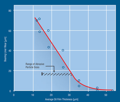
Figure 1. Increase in Journal Bearing Wear as Particle Size Exceeds the Minimum Film Thickness (Broeder and Heijnkemp)

Table 2. Typical Filtration in Circulating Oil Systems
In general, a filter selected with a nominal rating to match these requirements will remove the majority of larger particles. It must be kept in mind, however, that too fine of a filter may be undesirable because of the possibility of clogging, which requires frequent maintenance. Also, because of the large pressure drop across a filter, the power losses could become excessive.
Despite this particle size criterion, little damage is expected with soft contaminants such as fragments of cloth, paper, plastics and other particles with less than approximately one-third the hardness of the lubricated surfaces.
Isolated hard particles such as weld beads or metal chips can also be accommodated without significant damage by embedding in the soft babbitt lining of an oil-film bearing. This occurs only if particles fully embed themselves into the liner.
However, an abrasive contaminant can plow through the lining and bridge itself across the gap between the shaft and the bushing. In addition to scoring the shaft, there is the possibility of high local temperatures leading to scuffing and bearing failure.
Wear can be accelerated by a machine rotating at reduced speeds which reduces the lubricant film thickness. For instance, during normal operating speeds, fine fly ash will pass freely through machinery bearings in a coal burning electric power station without causing damage.
However, when the rotational speed drops to five to 10 rpm, the bearings in a steam turbine are susceptible to excessive wear due to reduced film thickness and the associated reduction in the clearance for the contaminants.
The same situation may be encountered in sleeve or ball bearings of a fan during slow-speed windmilling. Research also shows that in hydrodynamic bearings there is a possibility for high frictional loss and temperature rise with large concentration of small particles.
Typical filter ratings for industrial circulating oil systems are provided in Table 2.
Filter Flow Characteristics. Cartridge elements in an oil filter chamber should match the oil flow, pressure drop limitation and contaminant level. Surface filters (Figure 2) are the first choice for limited amounts of solid contaminants in gas and steam turbines, compressors and electric motors.
These are mainly pleated paper filters that collect contaminants on their surface while allowing high flow rates with little pressure drop.
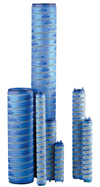
Figure 2. Pleated Paper-type Filter Cartridges (Courtesy Pall Corp.)
Depth-type filters should be considered for applications involving heavy levels of contamination, such as steel and paper mills. In these applications, surface filters would quickly lose their flow capacity.
Depth-type filters, on the other hand, are capable of removing particles throughout the depth of the filter material. Examples of these filters include cotton-waste packing, wound yarn, wire wool, fiberglass, cellulose and granular materials such as diatomaceous earth and activated alumina powder.
Wall thickness provides the depth-type filter cartridge with its large dirt-removal capacity. With wound yarn, for instance, the winding forms a myriad of storage cells for solid contaminants with only minimum flow resistance.
As dirty oil feeds though the outer periphery of each cartridge, contaminants are removed and retained in smaller storage cells next to the central supporting core. Dirt collection then progresses outward into cells of increasing size until the filter is loaded with dirt and must be replaced.
Adsorbent Filters. Using the surface-active properties of Fuller's earth, charcoal or activated alumina, absorbent filters remove polar materials such as water and oil oxidation products while serving as depth-type filters to remove solid contaminants from the oil.
Activated alumina filters extend the life of phosphate ester fire-resistant hydraulic fluids by removing initial degradation products. Too much water, however, destroys the effectiveness of absorbent filters as well as removes various polar type additives from the oil to degrade lubricant performance in turbine, paper-mill, hydraulic and other industrial applications.
Supplementary Oil Cleaning
A dirt load of 100 ppm in an oil is about the highest a depth filter can handle effectively. For higher concentrations of contaminants preliminary settling, centrifuging and/or a self-cleaning stage is needed.
Settling. Preliminary settling in the system reservoir typically provides optimum first stage oil purification. Larger particles and water settle to the reservoir floor, and most entrained air will be released at the surface when providing ample "dwell" periods.
For turbines, compressors and electric motors with low levels of contamination, about five to 10 minutes dwell time is needed. The settling time is about 30 minutes for lubricants heavily contaminated by water, metal scale and particle fines in steel and paper mill equipment.
To supplement settling, an off-line loop from the base of the reservoir (Figure 3) is often the best location for contaminant removal.
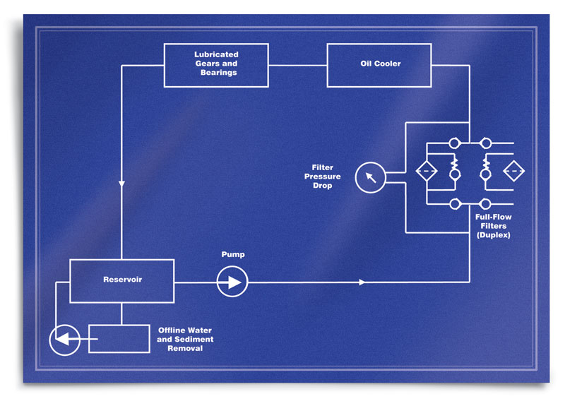
(Click Image to Enlarge)
Figure 3. Filtration in a Typical Lubrication System (adopted from Parkhurst)
Water Removal. Removing large quantities of free water is outside the capability of typical oil filters. For these applications, the use of settling or centrifugal separation drops the free water content in the oil to approximately 20 ppm above the saturation level.
Coalescing filter cartridges, absorbent type filters and vacuum chambers can also be used. More expensive gas sparging with air or nitrogen can be used to strip off dissolved and emulsified water without endangering loss of oil additives.
Free water, commonly in the form of relatively large droplets, is inexpensively removed from oil by settling, centrifuging or coalescing. The maximum water concentration in circulating oil systems should be held to the saturation level of about 300 ppm depending on temperature and lubricant formulation.
A lower level of around 100 ppm will minimize any long-term component damage. With 10 percent of the oil flow in the system being circulated through a bypass loop, approximately 0.1 to 0.3 gallons of water removal is commonly available per filter cartridge.1
Magnetic Filters. Commercial units with capacities up to 200 gpm use permanent magnets to remove iron and steel particles from oil in steel mill or metalworking operations and also from wear on machine elements. The magnetic filter is generally built into the oil piping for industrial gear sets, hydraulic units and turbine-gear drives with periodic disassembly and cleaning scheduled.
Bypass, Full-flow and Duplex Arrangements
Bypass filters were originally used in cars, steam turbines and a variety of industrial machines. With a small bypass stream of oil being continually filtered, wear from particle damage was minimized. Bypass filters allow finer filtration with a smaller pressure drop.
A bypass stream ranges from the 10 percent of the total flow rate (once common in automobiles, diesel engines and steel mills) to as little as two to five percent for steam turbines. Duplex filters in the bypass stream allowed periodic cleaning during operation by removing only one of the two parallel units at a time.
Full-flow filters have since become more popular than bypass filters. The full-flow filters provide only filtered oil throughout a machine. This minimizes the opportunity for damage to bearings, gears and other system components by large contaminant particles that would have missed the bypass filter.
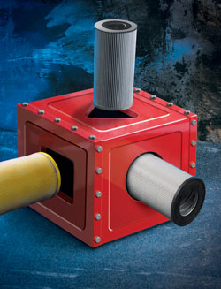
Duplex arrangement with two alternate filter units, such as those shown in Figure 4, allows the replacement of one of the full-flow filters when it becomes loaded with contaminant particles. For safety against lubricant starvation, a bypass valve will actuate when an overloaded filter element becomes plugged. Otherwise, the system would fail to deliver adequate oil feed.

Figure 4. Representative Filter Housings and Cartridges. Duplex Arrangement Allows Replacement of Contaminated Cartridges without Shutdown. (Courtesy Pall Corp.)
References:
1. Filtration Technology. Parker Hannifin Corp, Bulletin 0247-B1, 1997. (Available from Noria.)
2. L. Leugner. The Practical Handbook of Machinery Lubrication. Maintenance Tech. Inc. (Available from Noria.)
3. J.J. Broeder and, J.W. Heijnkemp. "Abrasive Wear of Journal Bearings by Particles in the Oil (Apparatus, Experiments and Observation)." proceedings of Mechanical Engineers, London, V. 180, p. 35-40, 1965-66.
4. J.K. Duchowski. "Examination of Journal Bearing Filtration Requirements." Lubrication Engineering, September 1998. p. 18-28.
5. H. Amirkhanian. "Advances in Centrifugal Filtration." Machinery Lubrication, July-August 2004. p. 34-36.
6. Y. El-Ibiary. "Extending Bearing Life and Performance." Machinery Lubrication, July-August 2004. p. 46-47.
7. H.J. Parkhurst. "Filter Element Service Life Evaluation and Optimization in Paper Machine Lubrication Systems." Lubrication Engineering, October 1994. p. 760-764.
8. M.M. Khonsari and E.R. Booser. Applied Tribology-Bearing Design and Lubrication, John Wiley & Sons, 2001.
9. M.M. Khonsari and E.R. Booser. "Effect of Contamination on the Performance of Hydrodynamic Bearings." Journal of Engineering Tribology, Proceedings of the IMechE, Part J, August 2006. p. 419-428.