Parasitic frictional losses in machines result in wasted energy and the generation of heat, which affects the life of materials, including the lubricant. A significant portion of total fluid film bearing losses in high-speed turbomachinery may be consumed simply in feeding oil to the bearings.
At surface speeds below roughly 10,000 ft/min, these extraneous parasitic losses are generally less than 10 percent of those of the oil-film frictional losses. For higher velocities, however, these losses increase rapidly with surface speed and can reach 25 to 50 percent of the total bearing loss in large turbine-generators and related machinery. This article discusses parasitic frictional losses in turbo machinery and suggests means for their reduction.

Sources of Parasitic Losses
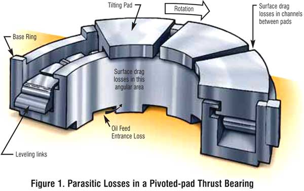
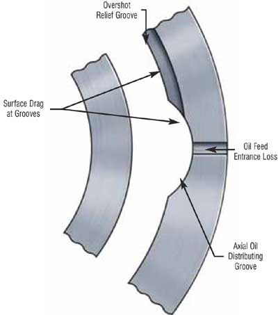
Parasitic losses for both journal and thrust bearings (Figures 1 and 2) can be assigned to two categories: through-flow loss simply caused by the lube oil’s passage through a bearing, and surface drag between the lube oil and rotating surfaces. Due to larger diameter and large surface area, these losses are generally greater in thrust bearings.
Through-flow Loss
These losses result from three sources: acceleration of the oil as it enters feed ports, influx and outflux of lubricant to and from feed grooves, and discharge of the lubricant from the bearing (leakage). Through-flow losses for a pivoted-pad thrust bearing can be assigned to the following sources (Figure 1):
-
One single velocity head loss for oil entering at the shaft surface velocity. This loss is associated with the flow of the oil feed as it enters under the base ring, makes an abrupt turn, and is brought to the bulk oil velocity between the shaft outside diameter and the inside diameter of the base ring.
-
One single velocity head loss, calculated at the mean thrust runner diameter, for the oil as it passes into the channels between the tilting pads and into the bearing oil film.
- Approximately 25 percent of discharge oil is assumed to be splashed onto the thrust runner to be reaccelerated at the runner’s outside diameter. This action is not typically encountered in conventional journal bearings.

Figure 1. Parasitic Losses in Journal Bearings
Referring to Figure 2, a plain cylindrical axial-groove journal bearing introduces a total parasitic loss of 1.5 velocity heads (calculated at the shaft surface velocity). This results from acceleration of the feed oil as it enters into the turbulent vortex in the feed groove and then further accelerates as it enters the bearing oil film itself. In pivoted pad journal bearings, on the other hand, vortex action and churning in the square-sided cavity between pads offers more resistance to entering feed oil.
Surface Drag Losses
Power loss from fluid friction drag on wetted shaft and thrust collar areas follows the general turbulent relation for hydraulic drag in channels where frictional loss is related to the dimensionless Reynolds number. For circular annular spaces around a journal, and for overshot internal grooves, as in the upper half of some journal bearings, the estimate of drag coefficient should be increased by 30 to 40 percent These losses would be reduced by appropriate draining of the housing to avoid fully-flooded operation.
Reducing Parasitic Losses
Several strategies may be employed to minimize parasitic losses in high-speed bearings. The simplest is to reduce the oil feed volume. A method that nearly eliminates the through-flow losses in fixed-pad bearings is discussed in the next section. For pivoted shoe bearings, feeding the oil directly to the leading edge of each bearing pad is an attractive method for decreasing parasitic power losses.
Decreased Loss with Partially Filled Grooves
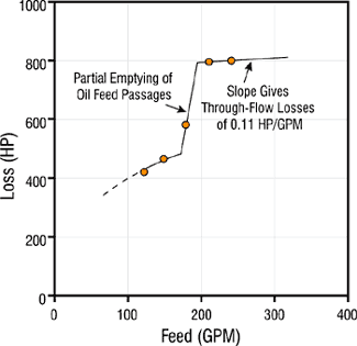
When the oil feed rate drops to the extent that internal grooves in a bearing are not completely filled with oil, the parasitic drag loss in the groove also drops, frequently to a negligible level.

Figure 3. Decrease in Power Loss in a 27-inch
O.D. Tapered Land Thrust Bearing Partially Filled
Figure 3 illustrates this point for a 350-square inch tapered-land steam-turbine thrust bearing operating at 3,600 rpm, wherein a step drop in power loss was encountered with decreasing oil flow. As the design oil feed was gradually reduced, at 166 gpm the total power loss in the bearing dropped from 800 to 473 hp. At this point, the back pressure dropped in the feed grooves with simultaneous elimination of through-flow loss for the entering oil.
Combined with observation of low loss in cavitated hydrodynamic oil films themselves, surface drag losses appear to become negligible for all partially filled zones within a bearing.
Leading Edge Feed Grooves
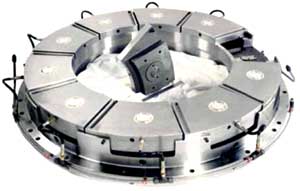
Several pivoted-pad bearing designs use sprays or channels to feed oil directly to the leading edge of each thrust pad in a bearing cavity otherwise empty of oil. These arrangements avoid essentially all surface drag losses which would otherwise be encountered by rotating surfaces immersed in oil as well as portions of through-flow losses.
Such designs are offered primarily for the surface speeds above that encountered in journal bearings with diameters approximately 10 to 12 inches operating at 3,600 rpm. For lower surface velocities, parasitic power losses become so low as not to warrant the extra cost and complexity with specially directed feed.
In high-speed bearings, leading edge oil feed grooves provide significant benefits. Oil flow rates can be as much as 60 percent lower with power loss down 45 percent. While a variety of lubrication flow arrangements, design and operating factors exert an influence, the resulting bearing temperature may be reduced by 16 to 35°F.

Figure 4. Pivoted Pad Thrust Bearing with
Leading Edge Oil Feed Grooves and Oil Lift
Pockets (Courtesy Kingsbury, Inc.)
As a surprising factor, reversing the rotation to place the oil feed groove at the trailing edge of each pad still provides satisfactory operation of a pivoted pad journal bearing at moderate speeds. This suggests that hot oil is still carried over from one pad to the next, and that absence of bulk oil from the bearing cavity is likely the major benefit to be realized from directed lubrication.
As bearing surface speeds range above approximately 10,000 ft./min., significant parasitic power losses may be encountered. At 30,000 ft./min., these losses may range up to half of the total power loss experienced in a bearing – equal to the power loss in the hydrodynamic load-supporting oil film itself. The following are factors to consider for minimizing parasitic frictional losses and achieving lower bearing temperatures:
-
Limit oil feed rate to the minimum required for reliable bearing operation.
-
Blend the shape of oil groove entrance ports and groove walls to minimize vortex flow restrictions.
-
Minimize unessential oil-wetted areas on rotating journal and thrust surfaces.
-
Minimize splashing of discharge oil onto rotating surfaces.
-
Utilize directed lubrication with leading edge grooves to feed tilting-pads.
References
-
Khonsari, M.M. and Booser, E.R. Applied Tribology: Bearing Design and Lubrication. John Wiley and Sons, New York, 2001.
-
Booser E.R. and Missana, A. “Parasitic Power Losses in Turbine Bearings.” Tribology Transactions, Vol. 33, pp. 157-162, 1990.
-
Vohr, J.H. “An Experimental Study of Taylor Vorticies and Turbulence in Flow Between Eccentric Rotating Cylinders.” ASME Journal of Lubrication Tech., pp. 285-296, 1968.
-
Heshmat, H. and Pinkus, O. “Mixing Inlet Temperatures in Hydrodynamic Bearings.” ASME Journal of Tribology, V. 108, pp. 231-248, 1986.
-
Kingsbury, Inc. High-efficiency LEG Thrust Bearings and related literature.


